 Davis Hydro, LLC
A Davis Collaborative
Company


Internal Pictures in Center Pier
Click on the pictures for higher resolution pictures. There are presented for use in discussion of best configuration.
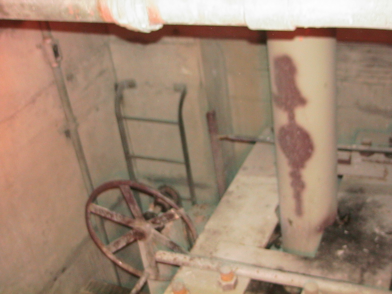 |
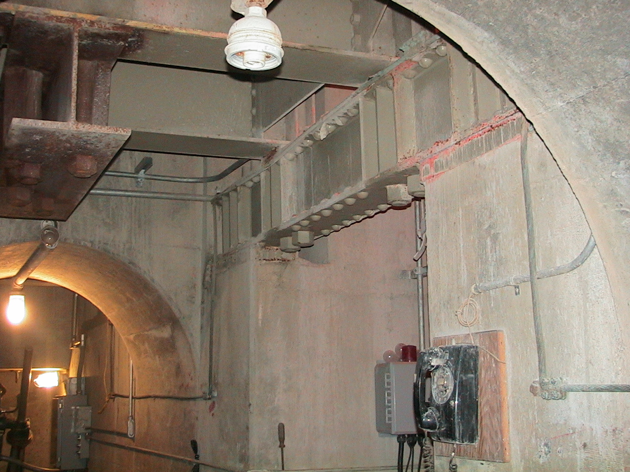
Cross I beam and Gate Shaft CoverAbandon equipment to be removed. The hand wheel was used to manually open and close the main gate. All three gates are identical. The new penstock will cone diagonally downwards at about 45 degrees through the wall on the left.
|
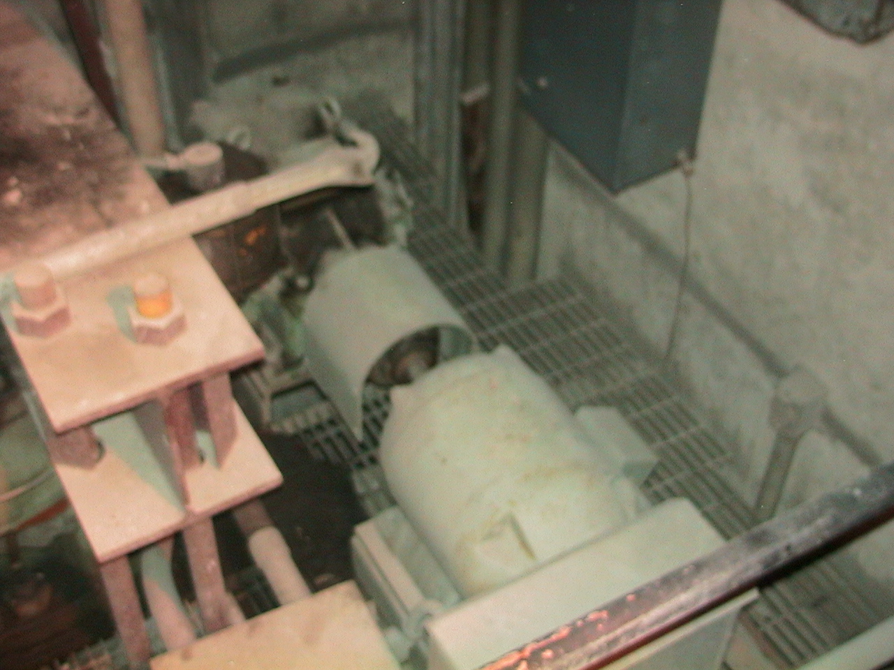 |
Abondon Gate Screwjack Motor and WorksTypical abandon gate actuation mechanism. All equipment in this picture will be removed. The power conduits from the gatehouse terminate in the panels such as the one shown at the top of this picture. |
 |
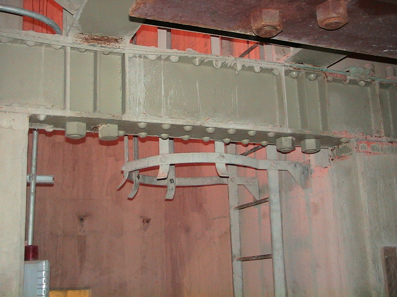
Conduit above new turbineHorizonal passage between gate chambers. The steel at the top of this picture is used to support the gate operator gear and motor for the gate. All three gates are identical. |
 |
Abandon Steel WorksPicture shows steel works that hold up abandon gate hoisting mechanism. Note that the inside of the dam is clean and dry. |
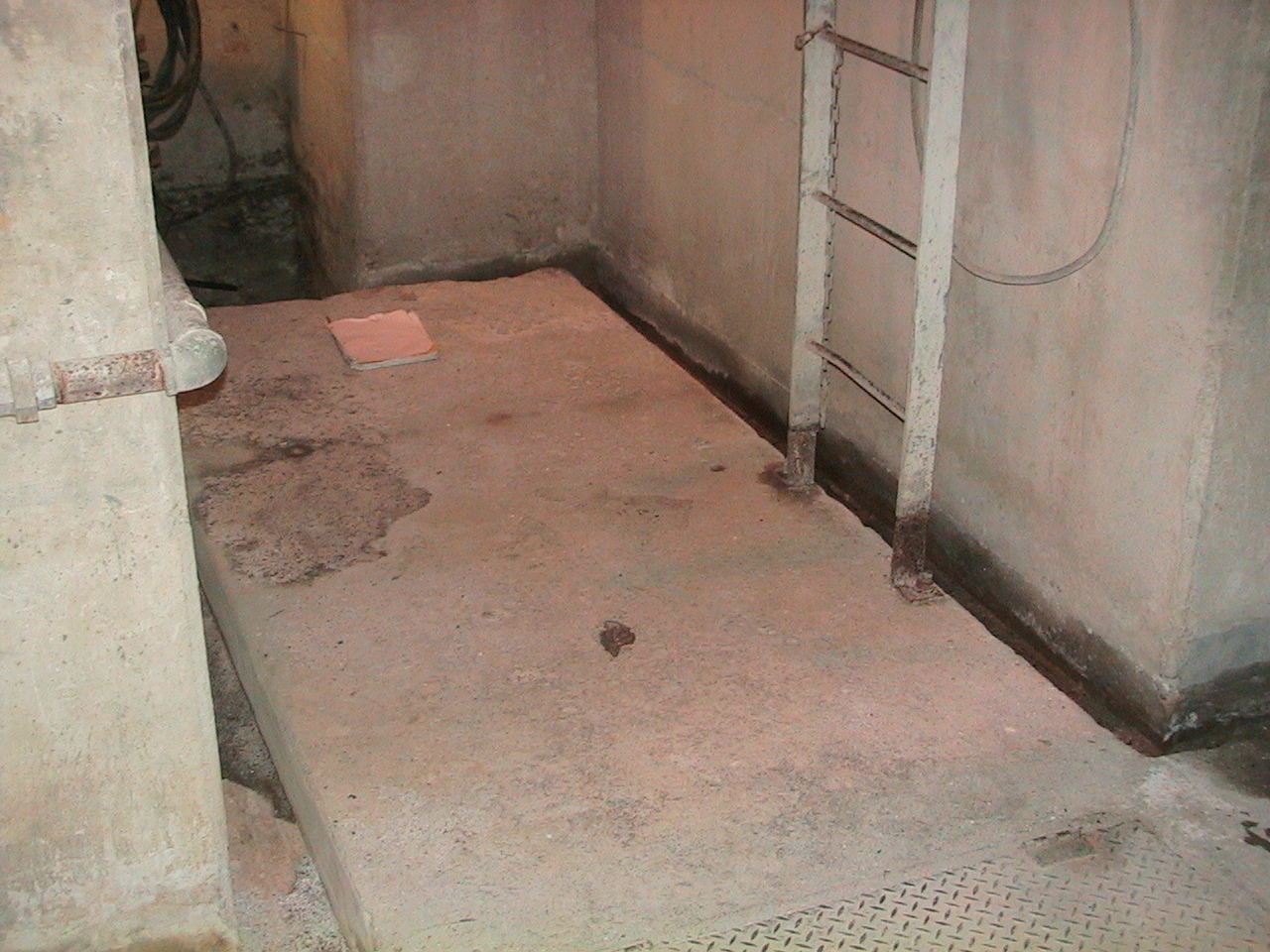 |
Vertical Shaft BottomThis photograph is taken from the most likely position of the new turbine looking downstream at the bottom of the 5 by 8 foot shaft. This area will be widened about 3 feet to accomodate a work and access area arounf the new turbine.
|
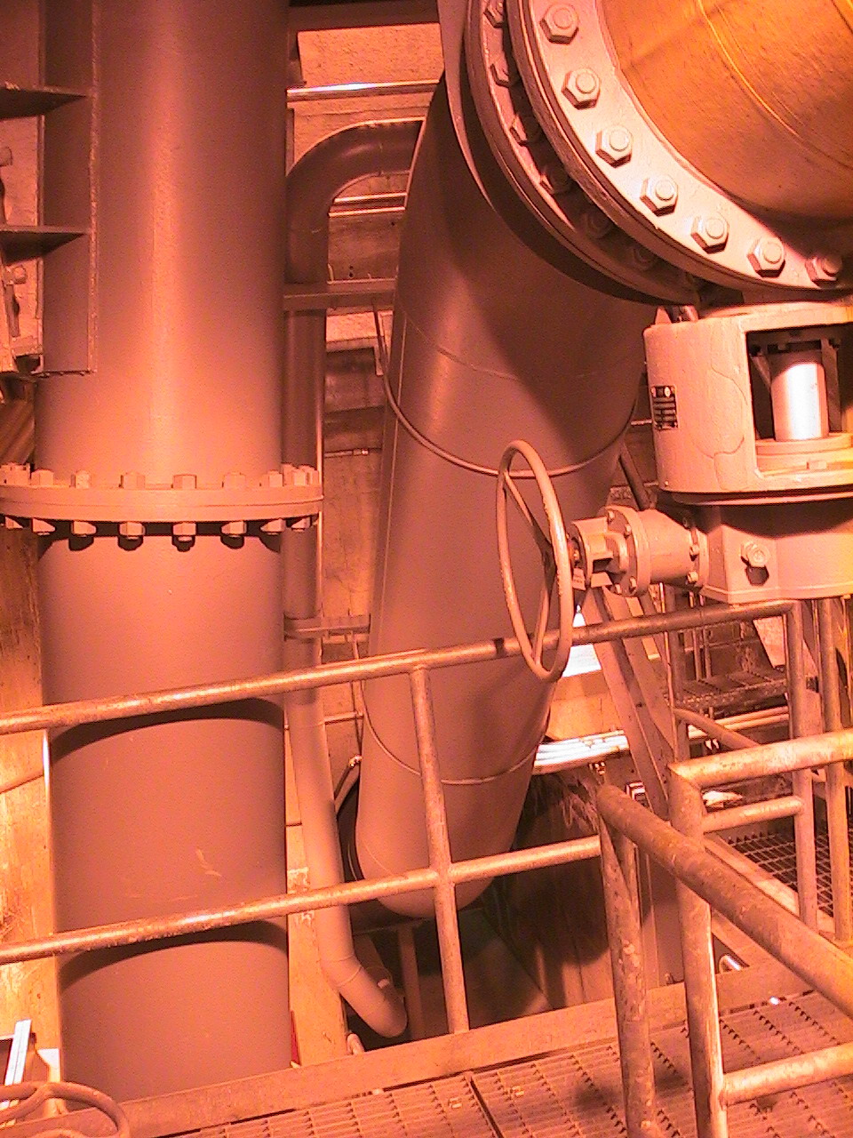 |
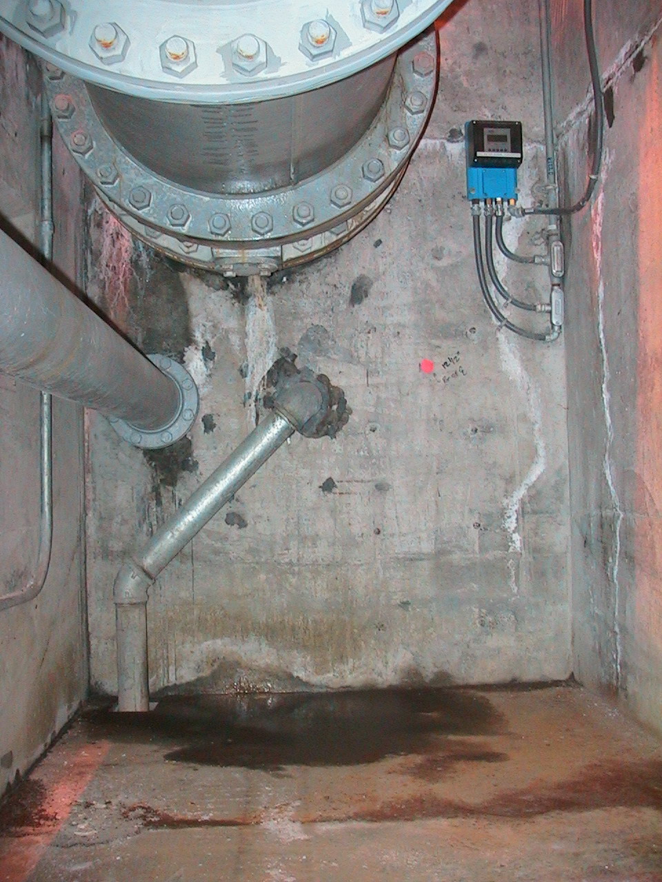
30" Pipe at 45 DregeesThe 45 degree slope where the 30" river release pipe changes levels. Proposed plans will be to change the lower 45 degree elbow to a bifurcation with the straight branch (shown here) continuing straight down at 45 degrees to a new turbine located in the lower gate chamber. Note the 30" manual check valve in the top right part of this picture. The flow gauge section will be moved to this area to measure total flow. The 24" pipe on the left is a drum gate drain pipe. These drain lines limit new piping placement. |
 |
30" Conduit Horizonally Leaving DamThis view is looking downstream from the location of the proposed tap. This photograph shows the removable portions of the 30" conduit including a flow metering gauging section as it leaves the dam. The parts of the pipe were made removable so that material could be lowered to the lower gate chambers down the shaft shown covered by a steel plate in the floor of this photo. The new turbine will be about 25 feet directly below the steel plate. This view will look the same when the new equipment is installed. The flow metering section will be moved upstream before the bifurcation so as to measure total flow to both the hydropower and the existing release port. |
© 2003, Davis Hydro
A Davis Collaborative Company
Web design/maintenance by Documagik