Turbine Setting Discussion
The Rock Creek Diversion Dam
Project
Version Dated : 12/16/2004
Turbine
setting:
The drawing
titled "Turbine Setting"
(Drawing # RC-T-3) is provided as a discussion sheet for turbine setting design.
Please refer to other drawings on this site and other drawings for
a complete understanding of the site. This
drawing is scaled for printing at 11 by 14 inches.
Equipment
Access:
The dam is
approximately 20 minute drive on state road 70 from motels/restaurants/hardware
in the town of Quincy. Rt. 70 leads
to the flat top of the dam. The site
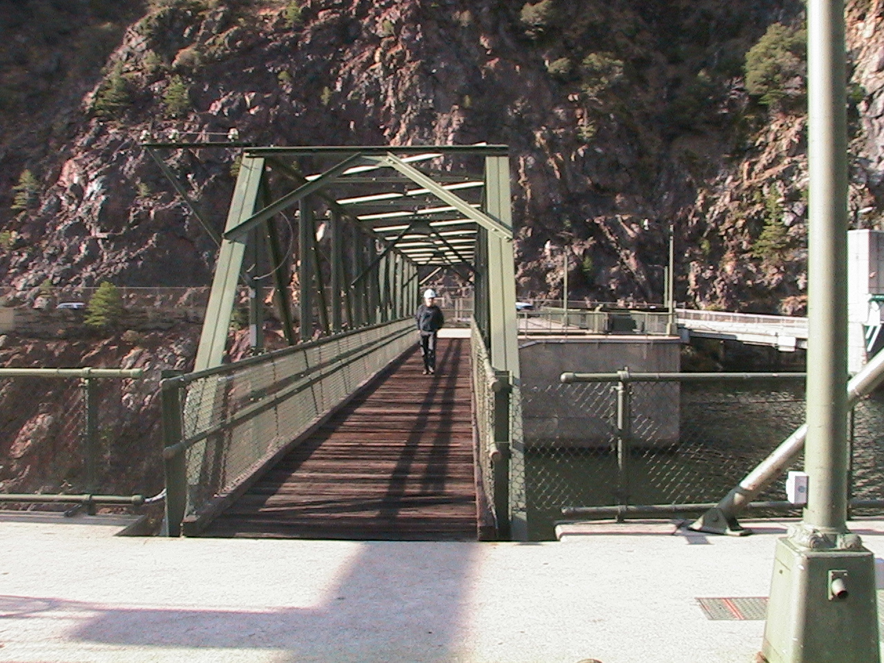
is about 2.5 hours North of Sacramento, or 1 hour East of Chico. Equipment must be brought from the road over
the bridge shown in photo "Bridge
to dam's central pier.JPG". Access to the dam top is level and directly
off a main road. Pieces too heavy
to pass over the dam catwalks could be come by barged. There is a crane on the front of the dam central pier.
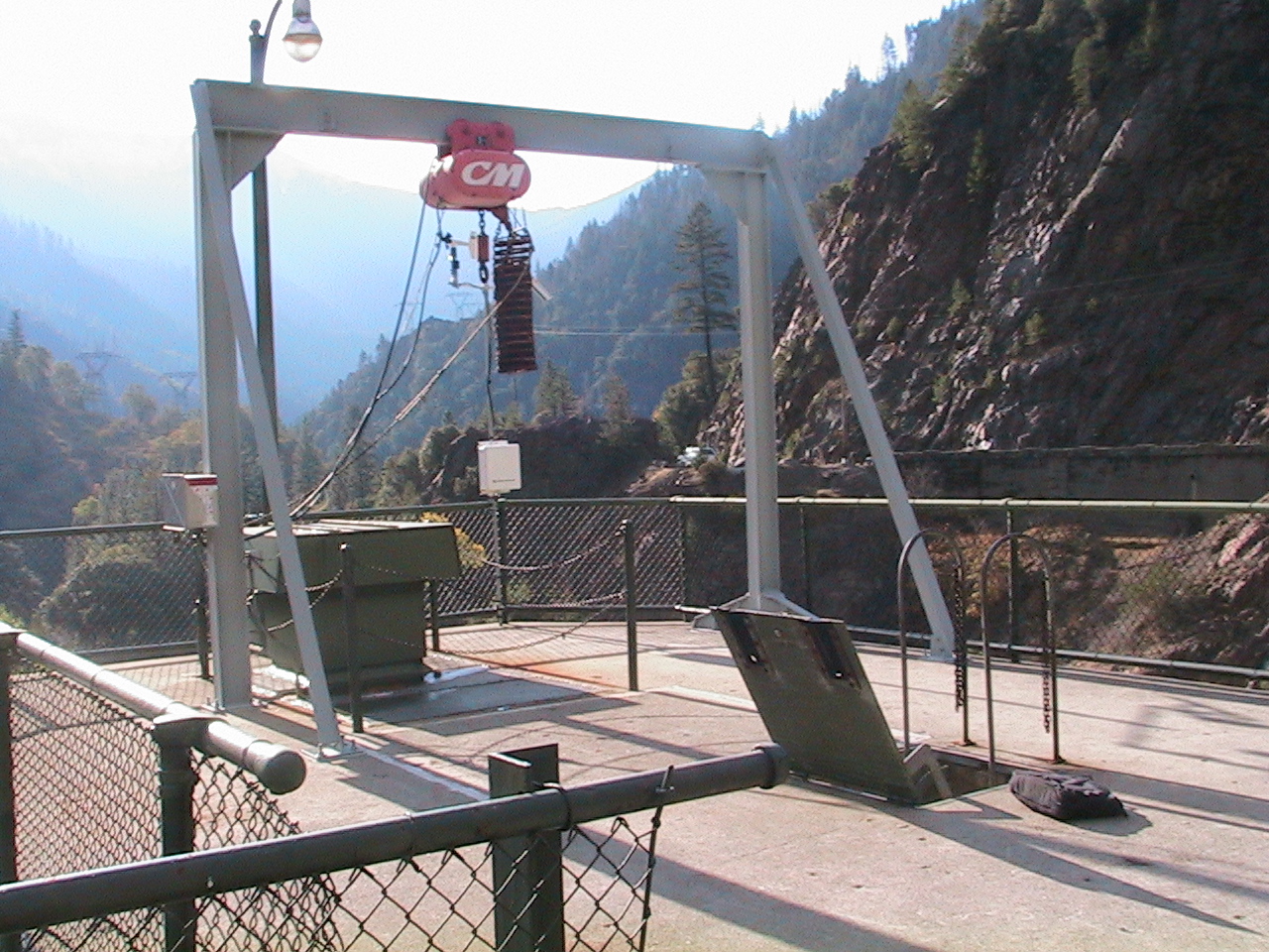
The 5’ x
8’ Vertical Shaft
There is
a 3 ton hoist shown in the photo titled "Hoist
on dam top over 5 by 8 foot shaft.JPG" over a 5 foot by 8 foot shaft
that drops all the way to the turbine floor.
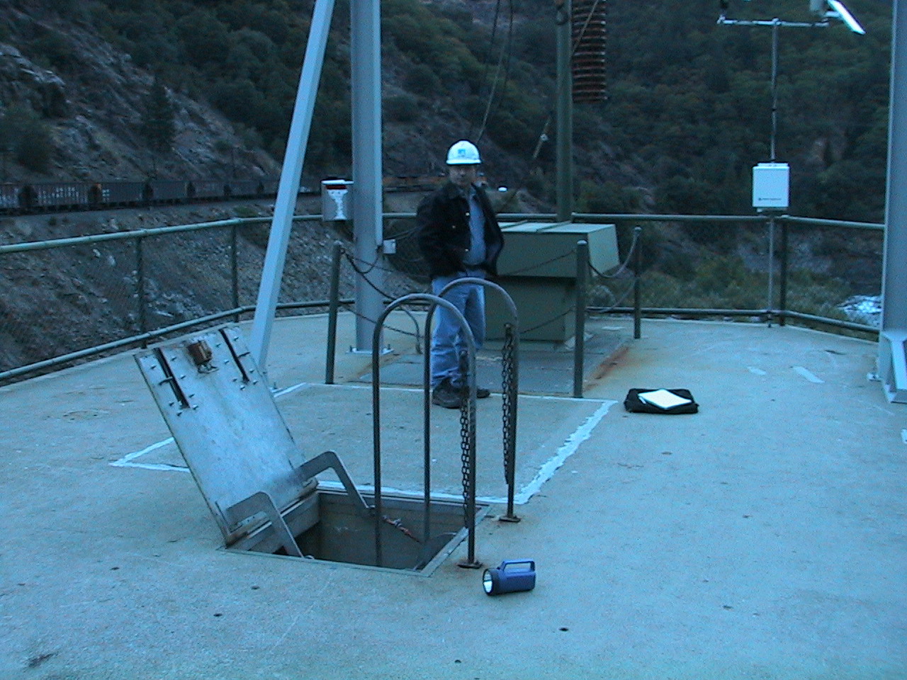
The turbine pieces must be lowered in pieces approximately 99' down
this 5' by 8' vertical shaft. The shaft top is shown from in photo "Shaft
Entrance on top of dam.jpg" using this hoist.
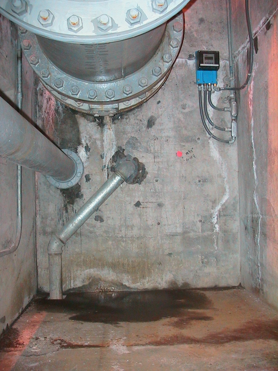
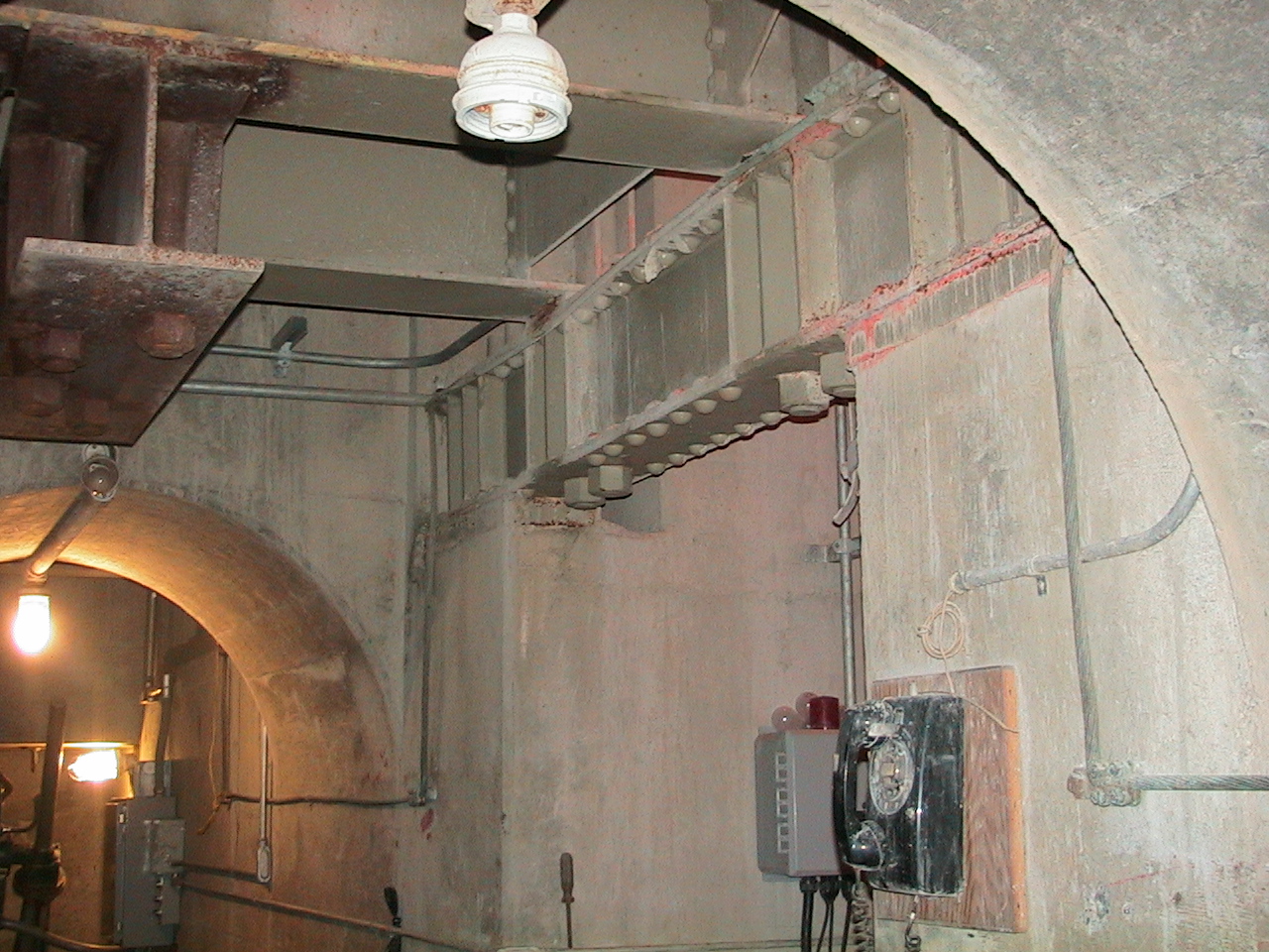
The
Existing 30 inch Feed Pipe
Part way
down this shaft is the horizontal 30 inch pipe currently carrying the fish
release water across the shaft for release as a jet onto the dam apron edge.
This pipe and a 6" pipe are removable to facilitate equipment
passage. The 30 inch pipe is shown
crossing the vertical shaft in photo titled "30
inch_pipe_level through shaft.jpg". The drawing RC-T-3 shows an elevation of the wall in this photo on its far
left. There is a removable thin metal floor under the pipe and a grill
over it. All of which are wrench removable.
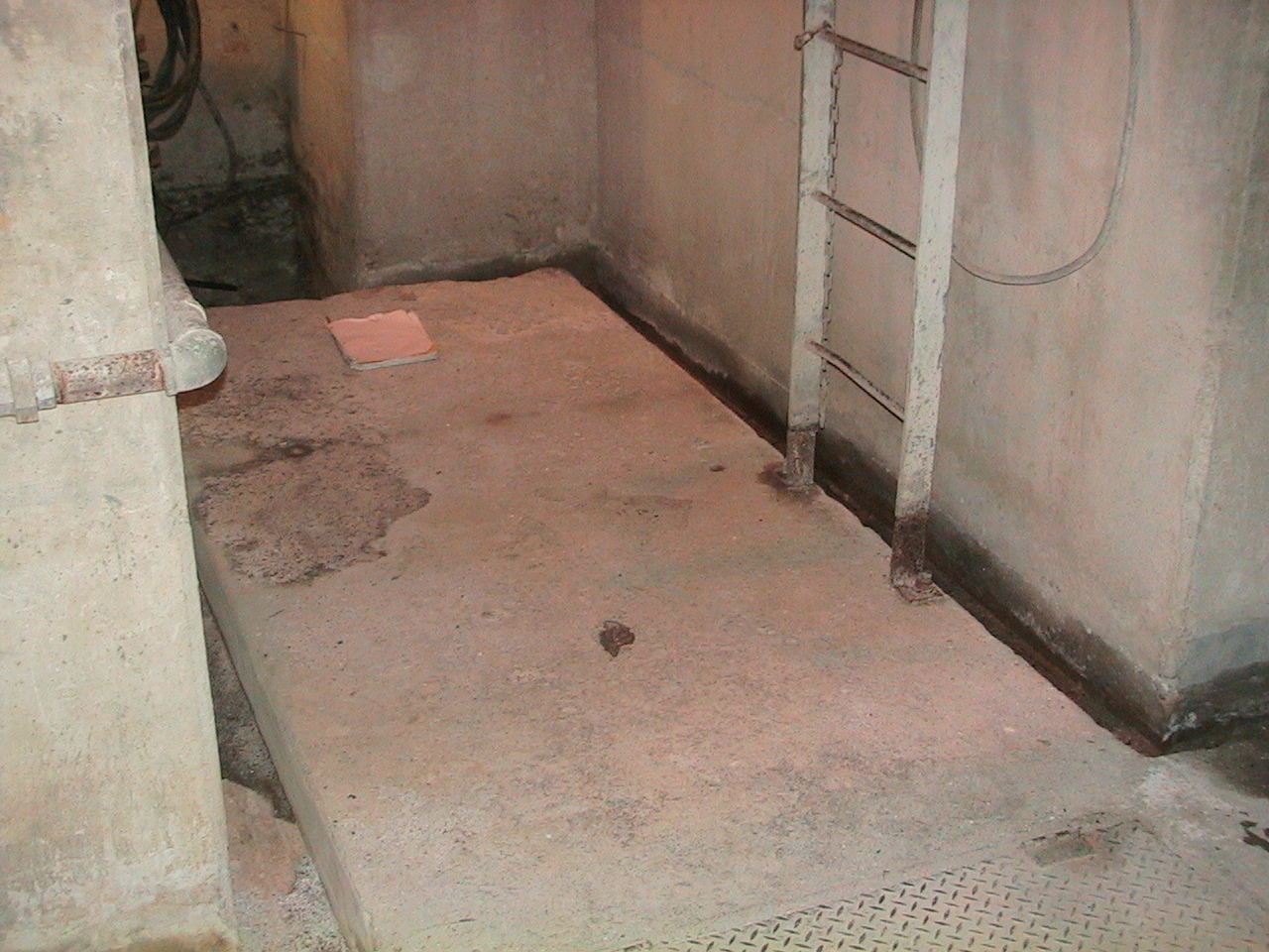
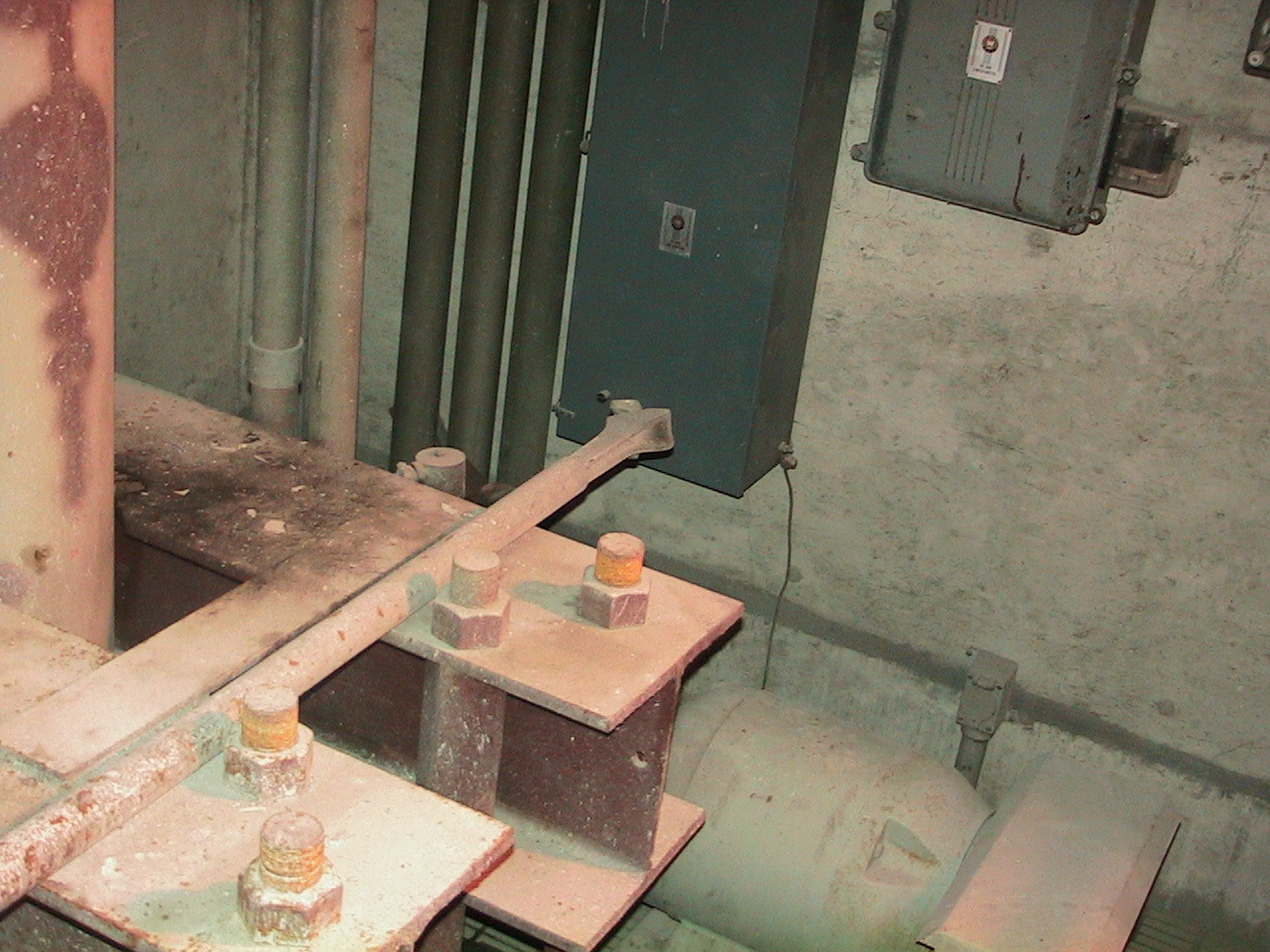
The
Turbine floor
This is
the main gate floor at the level of the bonnets of the abandon main gates. The screwjacks and motor actuators are in place
but disconnected at the switchboard. The
turbine mounting floor is shown in photo "Turbine_floor.JPG".
It is in two areas one the 5 by 8 foot flat area at the bottom of the
shaft and adjoining is a more spacious area just upstream (left) in the gate
mechanism area. The area where the
turbine is expected to go is in the general area of the “-T-”
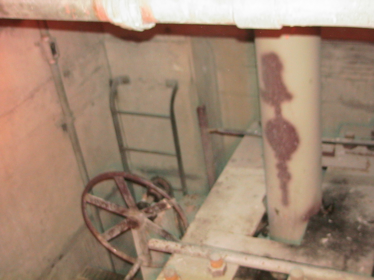
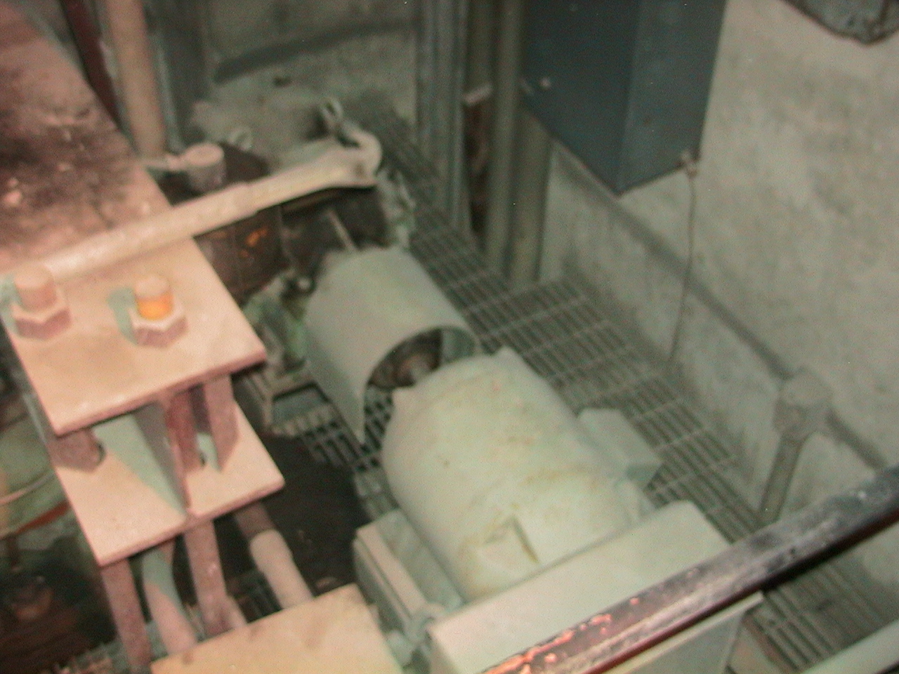
in this drawing. Working in this
area will require the removal of the gate hoisting equipment ( See Photos
"handwheel_gate_open_main_gates.JPG"
and "old
hoisting motors.JPG".) and its supports
that fills much of the middle of this area above the gate.
This is probably an acceptable design choice for a centrifugal turbine
design of the mixed flow or Francis type.
In the
lower right of the"Turbine Setting"
drawing is a suggested bifurcation of the 30 inch pipe that will bring the
water directly into the turbine floor area.
Other methods of bring water down would be a sharp bend into a vertical
column following the existing shaft. A
vertical turbine/pump would work this way.
This type of turbine would be limited by cavitation, however, there
is nothing to preclude lowering the runner base down in a new hole to close
to tailwater level. There is possibly more head available here
than needed, so the draft tube may not need to recover much of the velocity
head. This will allow a higher setting
of a runner.
The
setting problem is to install the largest turbine/generator possible while
removing as little concrete as is reasonable.
The equipment choice is to minimize installation, operation, and
maintenance costs.
The reservoir/tail
water head has a very small variation as this river is controlled for hydropower,
however, the 30" pipe imposes a severe flow/pressure constraint.
To estimate the losses, one would assume 6" head loss through
the trash rack (not shown on the setting sketch), a partly rounded corner
on the entrance to the pipe, and 5 year old steel 30" nominal steel pipe
with an assumed I.D. of 28.75 inches. Currently,
PG&E estimates that the maximum flow through the existing conduit is about
150 cfs as the pipe vents out to into the middle of the spillway at an elevation
of 2152.75 (PG&E datum). The calculations
shown in the power analysis spreadsheet
show a slightly higher maximum flow.